
Assisted Modeling
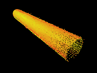
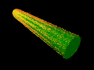
The idea behind Assisted Modeling is that the user identifies a point which belongs to an Asset or Primitive of a known type. For example, a point which belongs to a Cylinder Primitive is selected. It is then possible to automatically create an Asset or Primitive of that type, in this case a Cylinder Primitive, and "fit" it to the available laser scan point data.
|
|
Identify Element |
Automatically "Fit" Element |
In some cases there might not be enough point data to automatically create an Asset or Primitive, so there are additional Assisted Modeling tools that allow the user to create Assets or Primitive by picking two (or more) key points.

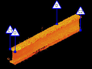
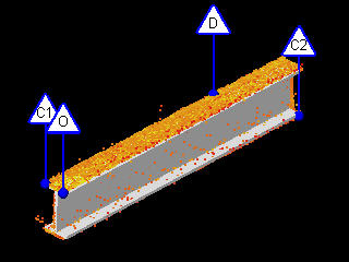
The "Complete" modeling tool requires the user to pick two corners of an Asset that are diagonally opposite each other. If the Asset or Primitive does not lie on a major axis, e.g. North, then additional points will need to be picked to specify the direction and orientation of the Asset or Primitive.
|
|
Identify Corners, Direction & Orientation |
Create element based on key points |

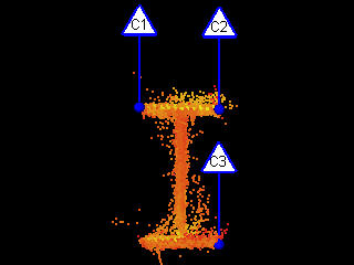
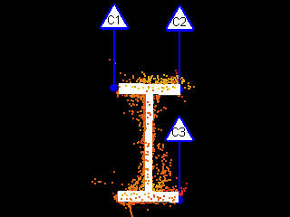
The "Cross-Section" modeling tool requires the user to key points which belong to the profile of an Asset.
|
|
Identify cross-section points |
Create element based on key points |
V-Suite CORE supports the Assisted Modeling of the following Primitives:


V-Suite CORE also supports the Assisted Modeling of any Assets that are based on these Primitives:


The following table shows the Assisted Modeling modes that are available for each of the supported Primitive Types:
|
Best Fit |
Complete |
Cross Section |
Boxes |
|
|
|
Cylinders |
|
|
|
Planes |
|
|
|
Steel |
|
|
|
Extrusion |
|
|
|


Catalog Modeling
When using the Assisted Modeling Tools if an Asset Catalog is available for the Asset being created then the user will be given the option to create an Asset from the Catalog. The Assisted Modeling Tool will first create the Asset using the specified points (or using available point cloud data) and then the Catalog’s Closest Match feature will be used to automatically pick the best Catalog Item from the Catalog.
 Auto-Connect
A powerful feature of Assisted Modeling is the auto-connect feature that connects the two most recently created Assets. This feature is supported by the Assisted Box Modeling Tool and the Assisted Cylinder Modeling Tool.
 Using the Camera Direction
When using the Cross Section modeling mode the camera can be used to specify the direction of the new Asset rather than using the three chosen Cross Section points to calculate the direction. This typically produces better results as calculating the direction can be very sensitive based on which points the user picks. For more information see the following sections: Assisted Box Modeling, Assisted Cylinder Modeling, Assisted Plane Modeling, Assisted Steel Modeling.

 Multiple Assets
When using the Assisted Modeling Tools for some assets, e.g. Cylinders or Straights, it is possible to simultaneously create multiple Assets. The idea is that the user can identify one or more Assets in the scene and then create them all at once. This feature can be useful when modeling from a large number of points and the creation of an Asset takes a few seconds to calculate. For more information see the following sections: Assisted Cylinder Modeling, Assisted Steel Modeling.
General Tips
Here are a few general tips for using the Assisted Modeling Tools:
- When using Best Fit for Boxes, Cylinders, Planes or Steel the percentage of Laser Scan / Scan Region points displayed affects the Assisted Modeling Tools. For example, if only 25% of the points are displayed the Assisted Modeling Tools will use the displayed points only when creating new Assets.
- The Assisted Modeling Tools typically evaluate the majority of the points that are displayed in the Asset Window. To improve performance and the accuracy of the results the user should display only the points required. This can be achieved by hiding Laser Scans or Scan Regions that aren’t required and/or clipping points that aren’t required.
- Picking different points can produce different results. So if a result is unacceptable then try again using different points or increase the display percentage of points.