
Cross Section Mode
 Cross Section Mode
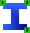
This mode creates Steel based on three key cross section points selected in the Asset Window.
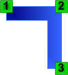
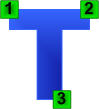
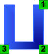
The cross sections for the different types of steel are shown below:
|
|
|
|
I-Shape |
L-Shape |
T-Shape |
U=Shape |
- Display a Laser Scan or a Laser Scan Region.
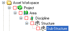
- Select an Asset in the Asset Explorer which is to be the parent of the new Assets.
- Choose the Assisted Steel Modeling Tool (
 ) by:
) by:
- Clicking on the Assisted Steel Modeling Tool button on the Asset Window Toolbar.
- Using the Assisted Modeling menu which can be found on the Asset View Menu.
- Using the default keyboard shortcut “F8”.
See Asset Steel Modeling for more information.
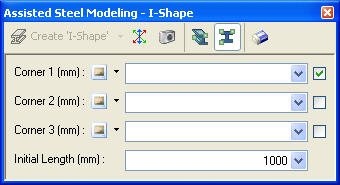
- Choose Cross Section Mode (
 ) in the Assisted Steel Modeling Dialog.
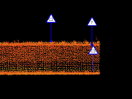
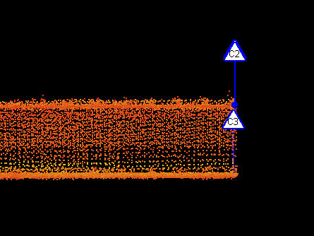
- Follow the on screen instructions and pick the required points. See Picking Points for more information.
- Once the user has chosen all three points a new 3D Element / Asset can be created. The direction of the new 3D Element / Asset is determined in one of two ways:
- If the user enabled "Use Camera Direction"
 then the current direction of the camera will be used as the direction of the new 3D Element / Asset.
 - If "Use Camera Direction" is not enabled then the direction will be calculated using the 3 chosen points and it is important to ensure that the chosen cross section points all lie on the same plane otherwise the new Asset will be orientated incorrectly.
|
All three cross section points are offset from one another, this will result in a mis-aligned steel 3D Element / Asset. |
|
All three cross section points are aligned, this will result in a well aligned steel 3D Element / Asset. |
- To create a 3D Element / Asset the user can either:
- Press SPACE to create the default 3D Element / Asset.
- Choose the 3D Element / Asset to create in the Assisted Steel Modeling dialog.
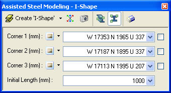
NOTE: The length of the new 3D Element / Asset cannot be determined from the cross section point so it will use the customizable "Initial Length" property.
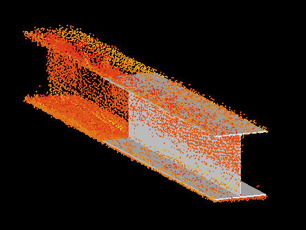
- A new Asset will be created, added to the Asset Explorer, and displayed in the Asset Window.
- To model another 3D Element / Asset the user can either:
- Click on another point in the Asset View which automatically clears the current marker.
- Press ESCAPE to clear the current marker and reset the Assisted Steel Modeling Dialog.
- Click Clear (
 ) in the Assisted Steel Modeling Dialog.