Laser Scan Display Styles
Laser scans are viewed in the Asset View window. Most actions performed on a model can be performed on a laser scan. These include:
- Taking point measurements (snap points are not usable with laser scan regions).
- Navigating through detailed laser scan region clouds.
- Note however, that laser scans which reference physical data which does not have a single scan's position will not support the Align-To command.
In addition, laser scans defined by a single scan's position allow the use of the Scan View tools to navigate from scan to scan while being fixed to the position of each laser scan.
Laser scans which are not defined by a single scan's position allow the use of the Asset View Toolbar.
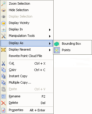
The display style for each laser scan can be modified depending on how the user wants to use the data. Laser scans may be displayed in different styles within the same window. The available display styles are:
- Bounding Box

|
|
Laser scans which reference point data coming from a single scan's position can be represented as a tripod. If such a laser scan is selected from the Asset View or the Asset Explorer, a bounding box is also displayed which is an approximation of the extent of the scan and includes all points captured by the laser scanner. The dimensions of the tripod and whether or not to display the bounding box when selecting the scan can be controlled through the Laser Scan Options. Laser scans which represent data from which a single scan's position can not be ascertained will always display as a bounding box.

|
|
Points displayed at Level 1. |
Points displayed at Level 2. |
|
|
Points displayed at Level 4. |
Points displayed at Level 5. |
Laser Scans can be displayed as the actual points captured by the laser scanner. The points are loaded from the external PCS file at the desired density as specified in the User Options. The file locations must be set in the Project Settings in order to locate and load the file.
You can display the points in either intensity color scale or grey scales using the User Options.
You can increase or decrease the number of points displayed by:
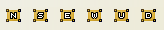
- Using the buttons in the Asset View toolbar

 .
. - Using the '+' or '-' keys on the Number Pad section of the keyboard.
- Right-clicking on the Laser Scan Detail setting on the Status Bar.
The number of levels can be configured through the User Options. Please note that the zoom level may also influence how many points are displayed.
Additionally, you may clip points out of the view using the Clipping Tools.
The display style change is done using either the Asset View Toolbar.

or the Display As command on the context menu.