
Attachments
The following table shows which Primitives can be attached to other Primitives.
|
|
|
|
|
|
|
|
|
Box |
|
|
|
|
|
|
|
|
Cone |
|
|
|
|
|
|
|
|
Cylinder |
|
|
|
|
|
|
|
|
Dish |
|
|
|
|
|
|
|
|
Pyramid |
|
|
|
|
|
|
|
|
Rect Torus |
|
|
|
|
|
|
|
|
Torus |
|
|
|
|
|
|
|
|


The following table shows which Assets can be attached to other Assets.
|
|
|
|
|
|
|
|
|
|
|
|
|
|
|
|
|
|
|
|
|
|
|
Angle Valve |
|
|
|
|
|
|
|
|
|
|
|
|
|
|
|
|
|
|
|
|
|
|
Blind Flange |
|
|
|
|
|
|
|
|
|
|
|
|
|
|
|
|
|
|
|
|
|
|
Branch |
|
|
|
|
|
|
|
|
|
|
|
|
|
|
|
|
|
|
|
|
|
|
Cap |
|
|
|
|
|
|
|
|
|
|
|
|
|
|
|
|
|
|
|
|
|
|
Duct |
|
|
|
|
|
|
|
|
|
|
|
|
|
|
|
|
|
|
|
|
|
|
Duct Bend |
|
|
|
|
|
|
|
|
|
|
|
|
|
|
|
|
|
|
|
|
|
|
Duct Reducer |
|
|
|
|
|
|
|
|
|
|
|
|
|
|
|
|
|
|
|
|
|
|
Elbow |
|
|
|
|
|
|
|
|
|
|
|
|
|
|
|
|
|
|
|
|
|
|
Flange |
|
|
|
|
|
|
|
|
|
|
|
|
|
|
|
|
|
|
|
|
|
|
Flanged Valves |
|
|
|
|
|
|
|
|
|
|
|
|
|
|
|
|
|
|
|
|
|
|
Gasket |
|
|
|
|
|
|
|
|
|
|
|
|
|
|
|
|
|
|
|
|
|
|
Inline Component |
|
|
|
|
|
|
|
|
|
|
|
|
|
|
|
|
|
|
|
|
|
|
Nozzle |
|
|
|
|
|
|
|
|
|
|
|
|
|
|
|
|
|
|
|
|
|
|
Reducer |
|
|
|
|
|
|
|
|
|
|
|
|
|
|
|
|
|
|
|
|
|
|
Reducing Elbow |
|
|
|
|
|
|
|
|
|
|
|
|
|
|
|
|
|
|
|
|
|
|
Safety Valve |
|
|
|
|
|
|
|
|
|
|
|
|
|
|
|
|
|
|
|
|
|
|
Spectacle Blind |
|
|
|
|
|
|
|
|
|
|
|
|
|
|
|
|
|
|
|
|
|
|
Straight |
|
|
|
|
|
|
|
|
|
|
|
|
|
|
|
|
|
|
|
|
|
|
Tee |
|
|
|
|
|
|
|
|
|
|
|
|
|
|
|
|
|
|
|
|
|
|
Valves |
|
|
|
|
|
|
|
|
|
|
|
|
|
|
|
|
|
|
|
|
|
|
Wafer Check Valve |
|
|
|
|
|
|
|
|
|
|
|
|
|
|
|
|
|
|
|
|
|
|


Attach also supports Macros. The following table shows which Macros can be attached to other Assets.
|
|
|
|
|
|
|
|
|
|
|
|
|
|
|
|
|
|
Angle Valve With Flanges Assembly |
|
|
|
|
|
|
|
|
|
|
|
|
|
|
|
|
|
Butterfly Valve (Custom) With Flanges Assembly |
|
|
|
|
|
|
|
|
|
|
|
|
|
|
|
|
|
Flange Pair |
|
||||||||||||||||
Flanged Check Valve With Flanges Assembly |
|
|
|
|
|
|
|
|
|
|
|
|
|
|
|
|
|
Flanged Valve (Custom) With Flanges Assembly |
|
|
|
|
|
|
|
|
|
|
|
|
|
|
|
|
|
Flanged Valve (Lever) With Flanges Assembly |
|
|
|
|
|
|
|
|
|
|
|
|
|
|
|
|
|
Flanged Valve (TBar) With Flanges Assembly |
|
|
|
|
|
|
|
|
|
|
|
|
|
|
|
|
|
Flanged Valve (Wheel) With Flanges Assembly |
|
|
|
|
|
|
|
|
|
|
|
|
|
|
|
|
|
Flanged Valve With Flanges Assembly |
|
|
|
|
|
|
|
|
|
|
|
|
|
|
|
|
|
Safety Valve With Flanges Assembly |
|
|
|
|
|
|
|
|
|
|
|
|
|
|
|
|
|


Outlined below is an example of how to attach a new Asset to an existing Asset.
- Display some Assets in the Asset Window
- Select "Connect" mode by either:

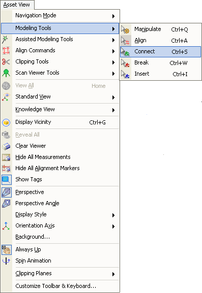
- Using a keyboard shortcut, see Assigning Keyboard Shortcuts for more information.
- Move the mouse cursor over the Asset to which the new Asset will be attached. The existing Assets Connection Points will be displayed. Pressing and holding the SHIFT key will display all the existing Assets Connection Points.
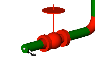
Moving the mouse over an Asset shows the Connection Point closest to the cursor
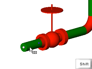
Holding the SHIFT key while over an Asset shows all the Connection Points for that Asset
- Once the desired Connection Point is highlighted left click the mouse to see a menu containing all the Assets that can be attached.
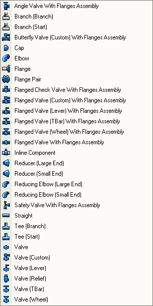
NOTE: If there is only one Asset that can be connected then no menu will be displayed and the new Asset will just be attached instantly.
- Choose an Asset, e.g. "Elbow", and it will be attached at the chosen Connection Point and added to the Asset Explorer under the same parent as the Asset to which it was attached.
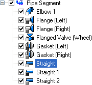
The Asset Explorer before Attaching a new Asset
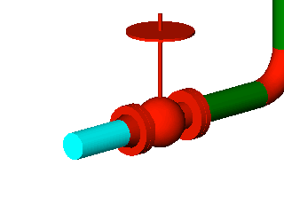
The Asset View before Attaching a new Asset
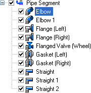
The Asset Explorer after Attaching a new Asset

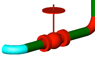
The Asset View after Attaching a new Asset
- Many Assets that can be attached in more than one way. For example, the Elbow that has been attached in this example has four different orientations; left, right, up and down. Pressing the SPACEBAR cycles through all the available options.
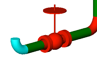
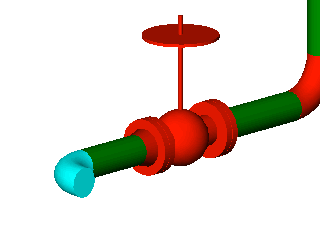
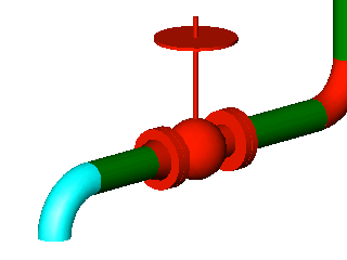
The SPACEBAR can be used to cycle through the four different orientations available when attaching an Elbow.