Measurement Tool Window
The Measurement Tool Window is used to manage point, distance and cylinder measurements and perform calculations. Calculations can be used to set positions, directions, orientations, dimensions, and diameters in the Property Dialogs.
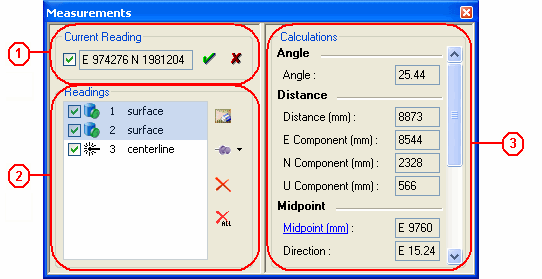
 Current Reading - Displays the East (E), North (N), and Up (U) values of the point clicked in the asset view. The current reading cannot be used in a calculations until the "Accept Current Measurement" button is clicked. Alternatively, the current reading may be accepted by using the SPACE bar while measuring in the Asset View. To delete the current measurement from the view window and from the Measurement Tool Window, click on the "Clear Current Measurement" button, which is denoted with a red "x".
 Readings - Displays accepted measurements that may be used in a calculations.
- The checkboxes indicate whether the point coordinates are displayed in the view window. Uncheck each one singly or click on the "Hide All Measurements" button.
- The default description of the Measurement may be changed by double-clicking on the name. This description is not saved in the database and it is only available for the current V-Suite CORE session.
- Create Marked Points by selecting a point and clicking on the "Create Marked Points" button.
 Calculations - Displays single point coordinates and distance and diameter calculations. This area is populated dynamically according to the points selected from the readings section. Multiple points may be selected by using the CTRL key.
- One Point Selected
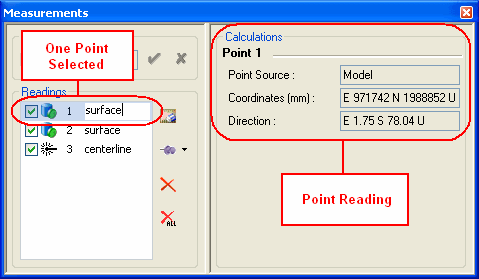
- Point X
- Point Source - Describes if the measurement was taken from a model or laser scan, or if it was calculated as a midpoint or center.
- Coordinates - The East, North, Up coordinates of the point. This coordinate or any of the individual components may be used in the position field of any asset property dialog.
- Direction - The direction of the normal at the surface where the measurement was taken. This direction may be used in the direction or orientation field of any asset property dialog.
- One Centerline Point Selected
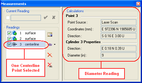
- Point X
- Point Source- Using laser scan for centerline measurements can only be taken from laser scans or regions
- Coordinates - East, North, Up coordinates of the centerline point closest to the surface point measured. This coordinate or any of the individual components may be used in the position field of any asset property dialog.
- Direction - The direction of the normal at the surface where the measurement was taken. This direction may be used in the direction or orientation field of any asset property dialog.
- Direction - The direction of the cylinder calculated from the centerline measurement. This direction may be used in the direction or orientation field of any asset property dialog.
- Diameter - The diameter of the cylinder calculated from the centerline measurement. This diameter may be used in any diameter field of any asset property dialog.
- Two Points Selected
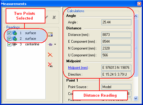
- Angle
- Angle - The angle between the directions of the two selected points. The direction of each point is the normal at the surface of the point measured. This angle may be used in any angle field of any asset property dialog.
- Distance
- Distance - Calculation of the linear distance between the two selected points. This dimension may be used in any dimension field of any asset property dialog.
- E Component - The distance in the east direction. This dimension may be used in any dimension field of any asset property dialog.
- N Component - The distance in the north direction. This dimension may be used in any dimension field of any asset property dialog.
- U Component - The distance in the up direction. This dimension may be used in any dimension field of any asset property dialog.
- Midpoint
- Midpoint - The midpoint between the two selected points. Clicking on the hyperlink will create another point reading at this coordinate.
- Direction - The direction from the first selected point to the second point. The order of the selection determines the direction. This direction may be used in the direction or orientation field of any asset property dialog.
- Three Points Selected
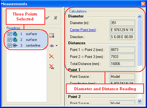
- Diameter
- Diameter - Calculation of the diameter between three points. This diameter may be used in any diameter field of any asset property dialog.
- Center Point - Center of the circle created by the three selected points. Clicking on the hyperlink will create another point reading at this coordinate.
- Direction - The normal direction of the circle created by the three selected points. This direction may be used in the direction or orientation field of any Asset Property dialog.
- Distances
- Difference between selected points: point 1 -> point 2
- Cumulative distance based on order of selection.
- Four or more Points Selected
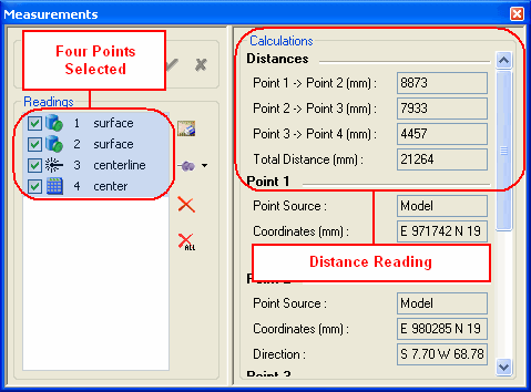
- Distances
- Difference between selected points: point 1 -> point 2
- Cumulative distance based on order of selection.
