
Assisted Surface Modeling Dialog
Once the Assisted Surface Model Modeling mode is activated the “Assisted Surface Model Modeling Dialog” will appear, allowing the user to choose how the surface model will be modeled.
Command |
Description |
||||
Surface Model Start point |
This field accepts a 3D point. The point may either be manually entered, or may be specified using the measurement selection drop down to the right. Alternatively, you may leave the default value ‘Derive From Point Extents’ if you do now wish to explicitly specify a surface model start point. The Surface Model Start Point will be used to specify where an edge of the triangles (which make up the surface model) must be located. This surface model start point will guarantee that a row/column of the surface model triangles will begin exactly where the Surface Model Start Point is specified.
|
||||
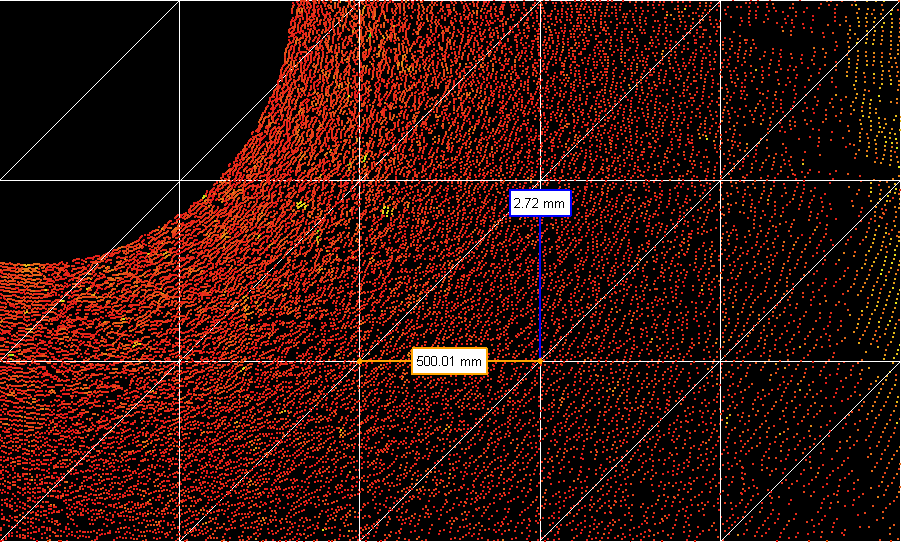
Surface Model Step Size |
This field indicates how smooth the surface model will be. The distance value indicates the length of the triangles used when creating the surface model; a smaller size, the smoother the surface model. Keep in mind, the smaller the size, the more triangles will be needed to create the surface model. The ideal value depends on the desired smoothness of the surface to be modelled. For flat ground, it may be recommended that a value of 1000mm be used, while for more undulating surfaces, better results will occur with smaller Surface model Step Sizes. The minimum value allowed is 100mm.
|
||||
Surface model Creation Location |
This field indicates where the surface model will be created in the asset hierarchy. The surface model will be created as an instance of the Asset Group template. Therefore, the desired location in the hierarchy must allow for the creation of this template. |
||||
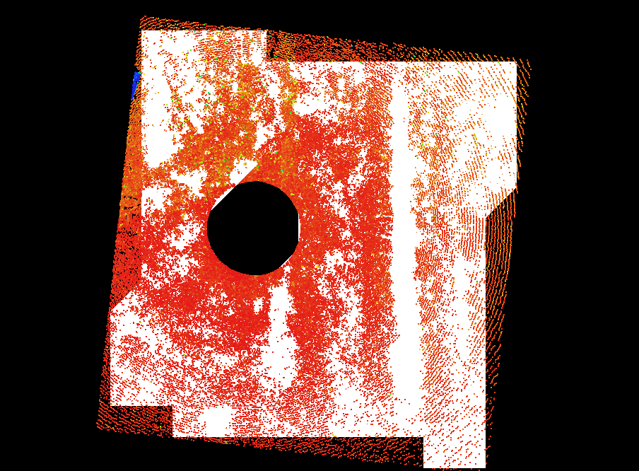
Fill Holes in Surface model |
This checkbox indicates if the surface model should interpolate missing point data so that holes are filled. If this field is unchecked, the surface model will only be created where there is physical data available. If this field is checked, the surface model will be created where there is physical data and also in places where physical data is missing. This interpolation of missing physical data will only occur when a hole exists in the surface model. It will not interpolate the surface model past the physical data’s extent.
|
||||
Perform Quick Physical Data Pass |
This indicates if the surface model processing should quickly scan the points displayed in the viewer, or if all points should be analyzed. Specifying this option will take less time to complete the surface model, however a more accurate surface model will be created if this box is unchecked. |
||||
Create Mutable Surface Mode |
This indicates if the created surface model should be compromised of many, individually modifiable triangles. If this option is unchecked, the surface model will be created as a small number of objects. Otherwise, if this option is checked, the surface model will be compromised of many objects, each representing a triangle in the surface model. Note that checking this option will result in a drastically increased time to complete the processing of the surface model. |
NOTE: The Assisted Surface Model Creation will process physical data that is displayed in the viewer. It will only consider points that are visible in the viewer. Performing clips of the physical data will cause clipped points to not be considered when the surface model is being processed. The surface model will be created as a group of triangles. These triangles will be organized in a column/number naming scheme such that the bottom left section of the surface model will be considered the lowest numbered Row/Column.